Craft a Clear-View Potentiometer to Demystify Variable Resistance
Introduction
Understanding how a potentiometer varies resistance is a cornerstone of electronics education. While commercial components are often opaque black boxes, building your own transparent version lets students and hobbyists see exactly how the internal parts interact. This guide walks you through creating a fully functional, visible potentiometer based on a design by [DiscoLapy]. The project uses a 3D-printed base and knob, a paper track coated with pencil graphite, and simple electrical contacts. By the end, you'll have a teaching tool that clearly demonstrates the relationship between mechanical position and electrical resistance.

What You Need
- 3D printer (or access to one) for printing the base and knob – PLA filament works well
- STL files for the potentiometer parts (see link in tips)
- Stiff paper or cardstock (e.g., 110 lb / 200 gsm) for the resistive track
- Standard graphite pencil (No. 2 / HB) – the graphite acts as the resistive element
- Scissors or craft knife
- Conductive materials:
- Small paper clips or copper tape for fixed contacts
- A metal wiper – bend a thin piece of brass shim or use a spring from a ballpoint pen
- Multimeter (to test resistance range)
- LED, resistor (approx. 330 Ω), and battery (3–5 V) for a demonstration circuit
- Alligator clip leads for easy connections
Step-by-Step Instructions
Step 1: Print the Mechanical Parts
Using the provided STL files, 3D-print the base and knob. Ensure the base has a central hole for the shaft and two slots for fixed contact pins. The knob should fit snugly over the shaft and include a small arm to carry the wiper. Print with standard settings (0.2 mm layer height, 20% infill) – accuracy matters most where the wiper will travel.
Step 2: Prepare the Resistive Track
Cut a semicircular strip of stiff paper about 1 cm wide and long enough to fit the arc of the base. Use a pencil to completely cover one side of the strip with graphite. Rub firmly and evenly – a dense, dark coating gives a lower resistance and better conductivity. Test with a multimeter: you should see a few hundred ohms from end to end. Tip: For a higher resistance (more sensitivity), apply less graphite; for lower resistance, lay down multiple heavy layers.
Step 3: Attach the Contacts
Place the graphite-coated paper track onto the base, aligning it with the two fixed contact slots. Insert paper clips or short pieces of copper tape into the slots so they press firmly against the ends of the track. These are your fixed terminals (A and B). Secure them with a drop of hot glue if needed. Ensure the track does not move – it must stay aligned with the wiper's path.
Step 4: Mount the Wiper
Take your metal wiper and bend it into an L-shape if it's not already formed. One leg will attach to the knob's arm, the other will ride along the graphite track. Attach the wiper to the knob using a small screw or by pressing it into a pre-drilled hole. The wiper must make firm, sliding contact with the graphite. Adjust the bend angle so it presses gently but doesn't gouge the paper.
Step 5: Assemble the Potentiometer
Place the knob onto the base's central shaft, aligning the wiper with the track. The wiper should now be positioned between the two fixed contacts. Rotate the knob – the wiper should sweep the full arc of the track from one end to the other. If it binds, lightly sand the edges of the paper or adjust the wiper's shape.
Step 6: Test Resistance Variation
Using a multimeter set to ohms (Ω), connect the probes across one fixed contact (A) and the wiper (C). Rotate the knob slowly and observe the resistance change. You should see a smooth increase or decrease as the wiper moves. The maximum resistance is between the two fixed terminals; the minimum is when the wiper is close to one end. If the reading jumps or is erratic, clean the graphite with a soft eraser and re-test.
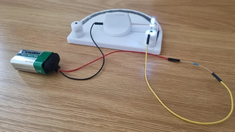
Step 7: Use in a Demonstration Circuit
Connect an LED and a current-limiting resistor (e.g., 330 Ω) in series with the battery and your homemade potentiometer. Use alligator clips: battery positive → fixed terminal A, wiper C → LED anode, LED cathode → resistor → battery negative. Rotate the knob – the LED will dim and brighten according to the resistance. This visual feedback makes the concept instantly clear. You can also insert the potentiometer as a voltage divider by connecting battery across A and B, and taking output from wiper C.
Tips for Success
- Download the STL files: Look for the original design by [DiscoLapy] on platforms like Thingiverse or Printables. Search for "transparent potentiometer" or "DIY teaching potentiometer".
- Graphite quality matters: Use a soft pencil (2B–6B) for a denser, more conductive coating. Hard pencils (H) give too much resistance.
- Protect the track – a thin layer of clear tape over the graphite can prevent smudging, but be careful it doesn't insulate the wiper contact.
- Calibrate for teaching: Draw tick marks on the base at 0°, 90°, 180° (if arc) to show where resistance is low, medium, and high.
- Make multiple tracks – you can create potentiometers with different graphite densities to demonstrate how material affects resistance range.
- Safety first: This is a low-voltage (<12 V) project. Do not use with AC mains or high currents – the paper track could overheat.
This clear-view potentiometer is an excellent addition to any electronics workshop or classroom. By literally seeing the wiper slide across the resistive material, learners grasp the concept of variable resistance intuitively. Adapt the design for other experiments – for example, use a longer track to make a linear slider, or add multiple taps to create a tapped potentiometer. Happy building!
Related Articles
- Human Expertise: The Real Driver of AI Success in 2025
- 10 Essential Steps for a Successful SOC 2 Type II Implementation
- Unraveling Python Memory Management: How CPython Handles Allocation, the GIL, and Internal Structures
- NVIDIA's Speculative Decoding Speeds Up RL Training by 1.8x at 8B Scale, with Projected 2.5x End-to-End Gain at 235B Parameters
- Revolutionizing Folder Navigation: How Zoxide Makes Windows File Explorer Feel Outdated
- 10 Ways the AI Revolution Is Shaping Your Career, According to NVIDIA's CEO
- Novice Programmer Develops AI Agent to Hack Coding Leaderboards: A Breakthrough in Agentic AI?
- Coursera and Udemy Merge to Form World's Largest Skills Development Platform